The working principle of a DC generator
Hello friends , Before explaining the working principle of a DC generator, we have to cover the basics of generators.
Hello students ,
Before explaining the working principle of a DC generator, we have to cover the basics of generators.
There are two types of generators
(1) DC generators and
(2) AC generators.
Both DC and AC generators convert mechanical power to electrical power .
A DC generator produces direct power, while an AC generator produces alternating power.
It's principal based upon the Faraday’s law of electromagnetic induction.
It states that "when the flux linking with a conductor changes then EMF induced in a conductor which will cause the flow of current when the conductor circuit is closed.
The magnitude of this induced EMF depends upon the rate of change of flux (magnetic line force) linkage with the conductor.
Essential components of simple loop generator:
1: The magnetic field
2: Conductors which move inside that magnetic

We will take the example of simple loop generator.
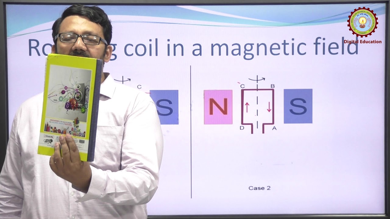
A single loop of conductor of rectangular shape of coil sides ABCD is placed between two opposite poles of magnet.
Let’s us consider, the rectangular loop of the conductor is ABCD which rotates inside the magnetic field about its axis ab. When the loop rotates from its vertical position to its horizontal position, it cuts the flux lines of the field. As during this movement two sides, i.e., AB and CD of the loop cut the flux lines there will be an EMF induced in these both of the sides (AB and BC) of the loop.
As the loop gets closed there will be a current circulating through the loop. The direction of the current can be determined by Flemming’s right hand Rule. This rule says that if you stretch thumb, index finger and middle finger of your right-hand perpendicular to each other, then thumbs indicates the direction of motion of the conductor, index finger indicates the direction of magnetic field, i.e., N – pole to S – pole, and middle finger indicates the direction of flow of current through the conductor.
Now if we apply this right-hand rule, we will see at this horizontal position of the loop, current will flow from point A to B and on the other side of the loop current will flow from point C to D.
Now if we allow the loop to move further, it will come again to its vertical position, but now the upper side of the loop will be CD, and lower side will be AB (just opposite of the previous vertical position). At this position, the tangential motion of the sides of the loop is parallel to the flux lines of the field. Hence there will be no question of flux cutting, and consequently, there will be no current in the loop.
If the loop rotates further, it comes to again in a horizontal position. But now, said AB side of the loop comes in front of N pole, and CD comes in front of S pole, i.e., just opposite to the previous horizontal position as shown in the figure beside.
Here the tangential motion of the side of the loop is perpendicular to the flux lines; hence rate of flux cutting is maximum here, and according to Flemming’s right-hand Rule, at this position current flows from B to A and on another side from D to C.
Now if the loop is continued to rotate about its axis. Every time the side AB comes in front of S pole, the current flows from A to B. Again, when it comes in front of N pole, the current flows from B to A. Similarly, every time the side CD comes in front of S pole the current flows from C to D., When the side CD comes in front of N pole the current flows from D to C.
If we observe this phenomenon differently, we can conclude, that each side of the loop comes in front of N pole, the current will flow through that side in the same direction, i.e., downward to the reference plane. Similarly, each side of the loop comes in front of S pole, the current through it flows in the same direction, i.e., upwards from the reference plane. From this, we will come to the topic of the principle of DC generator.
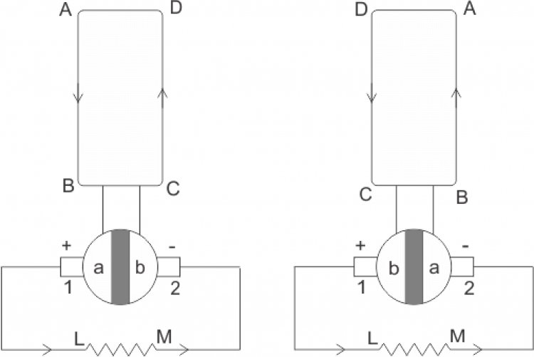
Now the loop is opened and connected it with a split ring as shown in the figure below. Split rings, made of a conducting cylinder, gets cut into two halves or segments insulated from each other. We connect the external load terminals with two carbon brushes which rest on these split slip ring segments.
Working Principle of DC Generator
We can clearly see that in the first half cycle of the revolution current always flows along ABLMCD, i.e., brush no 1 in contact with segment a.
In the next half revolution, in the figure, the direction of the induced current in the coil is reversed. But at the same time the position of the segments a and b are also reversed which is results that brush no 1 comes in touch with the segment b. Hence, the current in the load resistance again flows from L to M.
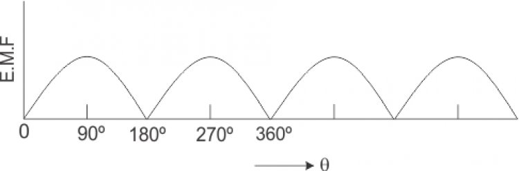
The waveform of the current through the load circuit LM is as shown in the figure. This current is always unidirectional.
This is the basic working principle of DC generator, which is explained by taking the example of simple loop generator having coil sides ABCD And resistance LM. The positions of the brushes of DC generator are placed in such a way that so that the change over of the segments a and b from one brush to other takes place when the plane of rotating coil is at a right angle to the plane of the lines of force. It is to become in that position, the induced EMF in the coil is zero.
So there are five principal components of dc generator .
(A) magnetic field
(B) conductors or group of conductors
(C) armature
(D) armature coil
(E) commutator
Students we will discuss later in my next post.
Hope you like it .for more post register on website .
Thanks
Gaurav tyagi


.svg)